
Fibre Cement Cladding Installation in Metro Vancouver
Clear module layouts and interface coordination for the specified fibre-cement system.
Modules
Coordinate the panel modules with the project elevations.
Openings
Review opening edges and joint arrangements together.
Attachment
Coordinate attachment references for the selected system and project requirements.
Closeout
Bring layouts, interface details and review comments into the agreed closeout.
Read the sequence and scope
- Modules. Coordinate the panel modules with the project elevations.
- Openings. Review opening edges and joint arrangements together.
- Attachment. Coordinate attachment references for the selected system and project requirements.
- Closeout. Bring layouts, interface details and review comments into the agreed closeout.
Presentation only. Follow the specified project documents, selected system requirements and agreed review responsibilities. The reference geometry is illustrative and not to scale. Existing service limitations and technical notes remain below.
Further service context and original reference images
Fibre cement cladding
A representative fibre-cement facade, shown as it is built from backing wall to finished panel plane.
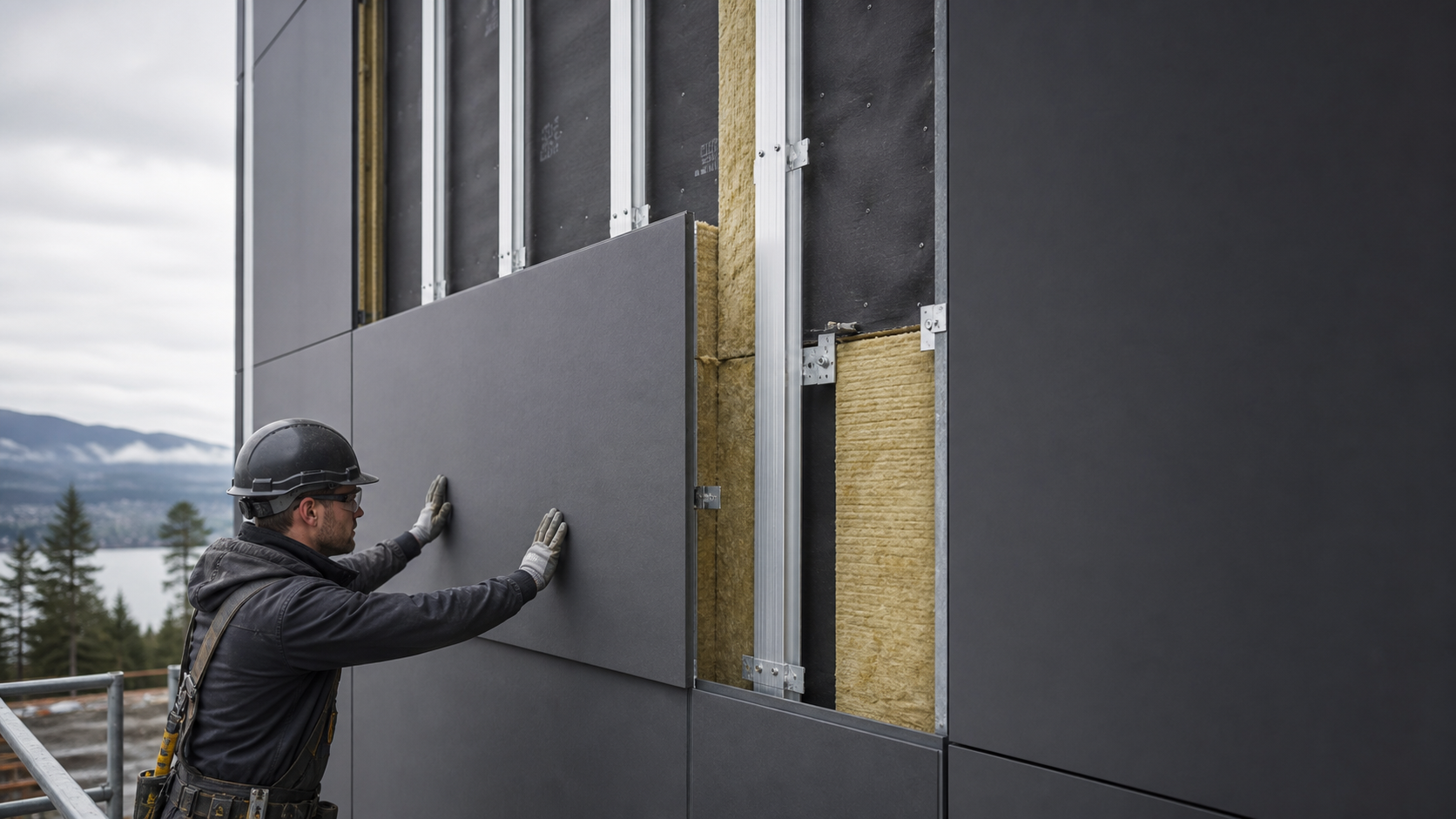
Original installation references and technical details
Prepare
Set a clean backing plane.
The detail is there when it is needed.
The animation leads. Project-specific technical information sits below it.
Technical note
Animations are representative and intended to explain general installation sequencing. Final construction must follow approved project drawings, specifications, engineering, consultant direction, manufacturer requirements, tested assemblies and applicable codes.
6-stage sequence transcript
- Prepare: Set a clean backing plane.
- Seal: Carry the weather layer behind the panels.
- Build out: Add insulation and a straight support plane.
- Lay out: Mark panel lines and edge trims.
- Install: Set panels with clear, even joints.
- Finish: Keep the drained cavity working behind the face.
Before construction
Final materials, fastening, transitions, flashing, substrates, continuity, engineering and project requirements must follow approved project documents and applicable requirements. Fig Philp Group Inc. should review the sequence against the selected system before construction.
See the assembly. Then send the drawings.
Share project drawings or request an exterior-cladding estimate from the Fig Philp Group Inc. team.
Representative installation sequence only — final construction follows approved project documents and applicable requirements.
- Prepare: Set a clean backing plane.
- Seal: Carry the weather layer behind the panels.
- Build out: Add insulation and a straight support plane.
- Lay out: Mark panel lines and edge trims.
- Install: Set panels with clear, even joints.
- Finish: Keep the drained cavity working behind the face.
Need panel layouts, trims and opening details on paper first? See our fibre-cement and cladding shop-drawing service.