Cladding shop drawings built around how facades are installed
Dimensioned panel layouts, opening details, flashing profiles and coordinated revisions for cladding contractors and fabricators across Canada, with remote support for projects in the United States.
Request a shop-drawing quote See a sample drawing set
Engineering design and professional sealing, where a project needs them, are separate services and are not part of a drafting quotation.
- Panel layout
- Matching schedule
- Opening detail
Canada-wide remote drafting; US enquiries welcome. Installation coverage is separate. Engineering design and professional sealing are separate services. Scope, timing and price are confirmed in the quotation.
AUTHORED ILLUSTRATION · NOT FOR FABRICATION

Panel layout → opening detail → matching schedule.
Read the demonstration
- The sample bay: backup wall, cavity, panels and joints.
- Panel layout: joints align to the openings; every panel has an ID.
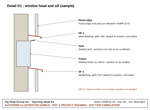
- Detail D1 at W1: folded head flashing HF-1 with end dams.
- The schedule matches the layout panel for panel.
The matching panel and flashing schedules and opening detail are in the sample drawing set below.
Illustrative dimensions and fold proportions only. “Issued for review” in the sample is not a project approval. Verified project sources and technical reviews govern.
See what you receive
Authored illustrative sample. It shows how a panel layout, its schedule and a coordinated opening detail are presented and cross-referenced. It is not a project drawing, is not taken from any client project, and is not for fabrication. Your project's specified system, verified dimensions and approved engineering govern.
Scroll sideways to see the full sheet.
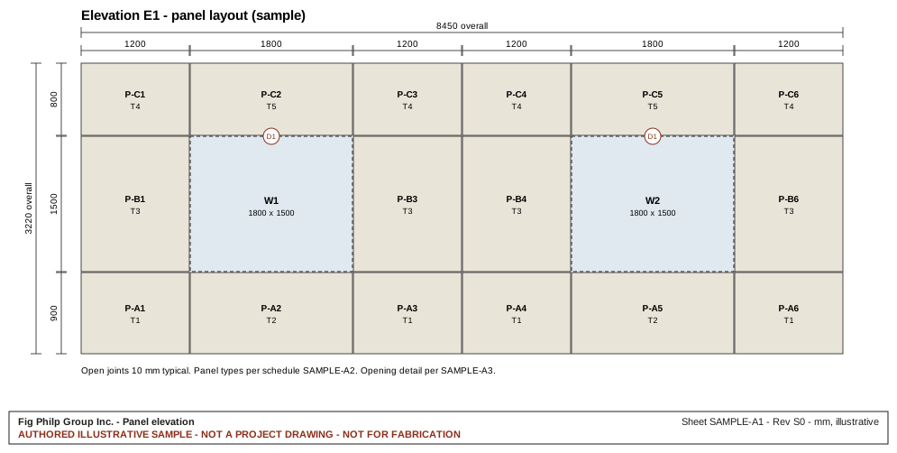
| Type | Size W × H (mm) | Qty | Panel IDs |
|---|---|---|---|
| T1 | 1200 × 900 | 4 | P-A1, P-A3, P-A4, P-A6 |
| T2 | 1800 × 900 | 2 | P-A2, P-A5 |
| T3 | 1200 × 1500 | 4 | P-B1, P-B3, P-B4, P-B6 |
| T4 | 1200 × 800 | 4 | P-C1, P-C3, P-C4, P-C6 |
| T5 | 1800 × 800 | 2 | P-C2, P-C5 |
| Profile | Opening | Girth (mm) | Length (mm) | Qty | Description |
|---|---|---|---|---|---|
| HF-1 | W1 | 185 | 1900 | 1 | Head flashing with end dams |
| HF-1 | W2 | 185 | 1900 | 1 | Head flashing with end dams |
| SF-1 | W1 | 210 | 1900 | 1 | Sill flashing with end dams |
| SF-1 | W2 | 210 | 1900 | 1 | Sill flashing with end dams |
| JT-1 | W1 | 120 | 1500 | 2 | Jamb trim |
| JT-1 | W2 | 120 | 1500 | 2 | Jamb trim |
What a drawing package can include
A useful shop-drawing package does more than repeat the architectural elevations. It shows how the specified cladding is arranged, where the panel joints fall, how openings and corners are handled, and which details and schedules apply to each area. Your quotation sets the exact scope. It may include:
- Dimensioned elevations with a panel ID on every panel.
- Panel schedules that match the elevations, by type, size and quantity.
- Window and door head, jamb and sill details.
- Base, corner, parapet and material-transition details.
- Flashing profiles with a schedule of girths, lengths and quantities.
- A set number of coordination and revision rounds, with a revision record.
Panel cutting lists, fabrication files, field measurement and as-built records are included only when your quotation says so. Information that has not been verified stays marked as a hold on the drawings instead of being guessed.
Drawings for the system on your project
Fibre-cement panels
Panel arrangements, joint alignment, returns and opening details for the fibre-cement panel system specified on your project.
ACM and MCM panels
Panel layouts, corners and returns, coordinated with the specified attachment system, with coordination drawings kept separate from fabrication outputs.
Metal cladding and flashings
Flashing profiles, system transitions and detail sheets. Describe the scope in your enquiry.
The manufacturer’s requirements for the specified product and the project’s approved engineering govern. Naming a product does not imply any affiliation with, or endorsement by, its manufacturer.
Choose the drawing support your project needs
Choose the drawing support your project needs
For profiled wall panels and specific opening or corner conditions, explore our metal-cladding and flashing drawings. Have an existing set with consultant comments? Ask about drawing revisions and redline support. Contractors and fabricators with several submissions can discuss project-based overflow drafting.
Need the finished face, wall build-out and material quantities coordinated against the building as measured? See facade alignment and material planning.
Start with the documents you have
Start with the documents you have
Tell us the project location, the cladding system, the drawings you need and your deadline. When you are ready, send the current architectural drawings, the relevant specification sections, addenda and any review comments. The submission checklist lists what helps most.
Use the short enquiry below if your document set is not ready yet. Use the secure upload form to send the current package. Receiving an enquiry or files does not confirm a delivery date and does not make any file a governing design document.
Drawings came back with comments?
Drawings came back with comments?
FPG can quote on revising panel layouts, answering coordination comments or providing overflow drafting for your drawing office. Send the comment set and the current project documents so the work can be scoped. We don’t promise that a consultant will accept a resubmission. We make the changes the comments call for and record what changed.
Where we work
Shop-drawing work is done remotely from Vancouver for projects anywhere in Canada. Enquiries from the United States are welcome. Units, responsible professionals, project information and commercial terms are confirmed for each assignment. Fig Philp Group Inc.’s installation crews work in Metro Vancouver and British Columbia; remote drafting does not extend that coverage, and FPG does not hold professional registration in every jurisdiction.
Can a US contractor use FPG’s drawing service?
US project enquiries are welcome. Include the state and city, required drawing units, cladding system, submission requirements and the responsible design professionals. Scope, formats, availability and commercial terms are confirmed for each assignment. Remote drafting is separate from installation and professional engineering.
How your drawings become a package
How your drawings become a package
Diagrammatic: the order a package is coordinated in — not a product, an approved assembly or a set of dimensions.

Fig Philp Group Inc. · illustrative workflow on a synthetic teaching sheet
This walk-through illustrates how FPG prepares a shop drawing, on a synthetic teaching sheet. It is teaching material, not a customer drawing, and not a claim that every package has already passed through every step shown.
- Source registered for review. Your PDF, DWG or photo is registered for review. It becomes a governing source only after a drafter confirms it; nothing is redrawn before that.
- Sheet calibrated. A drafter sets scale and page position against the confirmed source. Later measurements are in millimetres against this calibration, not estimated from the picture.
- Editable drawing built. Flashing profiles, openings and dimensions are drawn as editable objects that keep their source page, revision and author.
- Review with revision cloud. Reviewers mark changes with revision clouds and notes. Accepted changes are saved with a receipt; undo and redo stay in the project journal.
- Issued for review. The reviewed drawing package is issued for review with its revision and source references. Fabrication release stays conditional on the applicable checks and approvals; it is not an automatic step.
Your PDF, DWG or photo is registered for review. It becomes a governing source only after a drafter confirms it; nothing is redrawn before that.
A drafter sets scale and page position against the confirmed source. Later measurements are in millimetres against this calibration, not estimated from the picture.
Flashing profiles, openings and dimensions are drawn as editable objects that keep their source page, revision and author.
Reviewers mark changes with revision clouds and notes. Accepted changes are saved with a receipt; undo and redo stay in the project journal.
The reviewed drawing package is issued for review with its revision and source references. Fabrication release stays conditional on the applicable checks and approvals; it is not an automatic step.
Drawings are prepared by Fig Philp Group Inc. drafters from registered sources.
How a drawing becomes a package
Every step below is a coordination decision, not a drafting flourish. The sequence runs once, holds its finished state and stays reachable by keyboard. Geometry is diagrammatic and carries no dimension, gauge, spacing or product.
- 01Architectural elevation. The issued design drawing is the starting record.
- 02Facade zones and panel grid. Zones and a setting-out grid are traced over the elevation.
- 03Section cut. The elevation is cut and the view becomes a wall section.
- 04Substrate and barrier. Sheathing and the air and vapour barrier are documented first.
- 05Insulation and clips. Exterior insulation and the thermal clips that carry the outer frame.
- 06Rails and cavity. Rails or girts set the drained, vented cavity behind the cladding.
- 07Cladding and flashing. The finish plane closes with its flashings, trims and interfaces.
- 08Interface details. Base, parapet, corners, transitions, openings, end dams, weeps and screens expand.
- 09Source of record. Each fact is tagged to a drawing, specification, submittal, RFI or field check.
- 10Coordinated package. The sheets collate for project-team review. Unknowns stay visible as holds.
NTS — DIMENSIONS ON HOLD; NO GAUGE, SPACING OR PRODUCT IS SHOWN OR IMPLIED
Governing documents, scope and fasteners
Project drawings, specifications, approved submittals, manufacturer instructions and applicable codes govern. The FPG Detail Library is a controlled reference and generation resource and does not replace project-specific design or approval.
Scope responsibility varies by project — coordinate with the approved responsibility matrix.
Fasteners shown are illustrative only. Type, material, spacing, embedment, edge distance and structural capacity must follow the approved project design and manufacturer requirements.
Practical questions
Will the drawings include exact panel dimensions?
The agreed scope can include dimensioned panel layouts and a matching schedule. Final fabrication dimensions depend on verified project information and the required reviews. Unresolved dimensions are marked on the drawings, not guessed.
Are engineering calculations or a seal included?
Not in a drafting quotation. Any engineering a project needs must be scoped separately with a professional qualified in the project's jurisdiction.
Can you work with our engineer or fabricator?
Yes. Include their requirements and how you want coordination handled. Responsibilities, coordination rounds and deliverables are set out in the quotation.
What does a package cost, and how long does it take?
It depends on the systems, the size of the project, the detail required, the quality of the source documents, the number of revision rounds and any separate engineering coordination. Send the scope and your deadline and we will confirm both in the quotation. This page does not guarantee a price or a delivery date.
What file formats do you work from?
The secure upload form accepts PDF, DWG, DXF, image and ZIP files. Output formats are confirmed in the quotation, so tell us if you need a particular one.
Request a shop-drawing quote
Tell us about the project. You don't need to send drawings yet. If your document set is ready, use the secure upload form instead.
Enquiry received
FPG will review the scope and reply by email. This confirms that your enquiry was received. It is not a price, a delivery date or acceptance of drawings.
Ready to send documents? Use the secure upload form.