
Building Envelope Remediation Across Metro Vancouver
Documented conditions, agreed intervention and coordinated replacement interfaces.
Condition
Start with documented existing conditions and the defined scope.
Intervention
Coordinate the agreed intervention with the project team.
Interfaces
Review replacement interfaces against the project-specific details.
Closeout
Bring review comments and project records into the agreed closeout.
Read the sequence and scope
- Condition. Start with documented existing conditions and the defined scope.
- Intervention. Coordinate the agreed intervention with the project team.
- Interfaces. Review replacement interfaces against the project-specific details.
- Closeout. Bring review comments and project records into the agreed closeout.
Presentation only. Follow the specified project documents, selected system requirements and agreed review responsibilities. The reference geometry is illustrative and not to scale. Existing service limitations and technical notes remain below.
Further service context and original reference images
Building envelope remediation
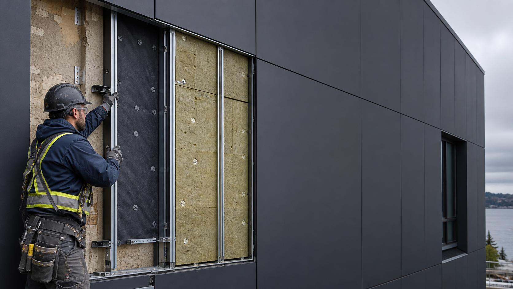
A representative remediation sequence: investigate, repair the wall below, reconnect the weather layer and rebuild the facade.
Original installation references and technical details
Assess
Look behind the outer finish.
The detail is there when it is needed.
The animation leads. Project-specific technical information sits below it.
Technical note
Animations are representative and intended to explain general installation sequencing. Final construction must follow approved project drawings, specifications, engineering, consultant direction, manufacturer requirements, tested assemblies and applicable codes.
6-stage sequence transcript
- Assess: Look behind the outer finish.
- Open: Remove affected layers with care.
- Repair: Restore the wall below.
- Reseal: Reconnect the weather layer.
- Rebuild: Add insulation, rails and a new skin.
- Review: Check the wall before closing.
Before construction
Final materials, fastening, transitions, flashing, substrates, continuity, engineering and project requirements must follow approved project documents and applicable requirements. Fig Philp Group Inc. should review the sequence against the selected system before construction.
See the assembly. Then send the drawings.
Share project drawings or request an exterior-cladding estimate from the Fig Philp Group Inc. team.
Representative installation sequence only — final construction follows approved project documents and applicable requirements.
- Assess: Look behind the outer finish.
- Open: Remove affected layers with care.
- Repair: Restore the wall below.
- Reseal: Reconnect the weather layer.
- Rebuild: Add insulation, rails and a new skin.
- Review: Check the wall before closing.
Animated remediation sequence
Project-specific reference details and governing notes
?step=N jump-and-hold at step N (one to fourteen) · ?reduced=1 force the
reduced-motion static annotated view · ?poster=1 hold the poster frame (no autoplay).
Keyboard: focus the diagram, then ←/→ step, Space play/pause.Transcript — the remediation sequence in words
The animation is muted and carries no audio track. This is its complete text equivalent: one entry per step, in build order, matching the on-screen captions.
- Step 01 — EXISTING FACE-SEALED WALL. The drawing opens on the wall as found. A generic face-sealed cladding runs across both bays, and the only thing standing between the weather and the structure is the panel face itself plus the sealant in its joints. There is no cavity behind that face, so there is nowhere for incidental water to go and no air path to dry it. Hairline cracking is marked at panel joints and failed sealant is marked at the window head and sill — the two places the wall is most often asked to be perfect and most often is not.
- Step 02 — CONCEALED MOISTURE DAMAGE. A cutaway wedge peels the face back at the work bay and the same wall is drawn honestly from behind. Staining tracks down the sheathing beneath the failed joints, the insulation in the stud bays is wet, and rot hatching sits on the sheathing and the framing edge below the window and along the base of the wall. Inward arrows trace the mechanism: water crosses the failed sealant line, meets no drainage plane, and is held against the sheathing. The extent drawn is illustrative — Note 5 governs, and the real extent comes from the investigation program.
- Step 03 — INVESTIGATION OPENINGS. Before any repair scope is fixed, targeted exploratory openings are cut and moisture testing is carried out. Three openings are drawn, each with a probe symbol, a record marker keyed to the drawings and a temporary weather closure reinstating it the same day. The moisture legend is deliberately qualitative — wet or dry — because no numeric reading exists for a generic drawing and none is invented. A hazardous-materials assessment marker precedes any disturbance of existing materials, per Note 6.
- Step 04 — PROTECTION + CONTAINMENT. The building is occupied throughout. Scaffold standards and ledgers frame the elevation, containment sheeting encloses the active zone inside a dashed boundary, and an overhead protection canopy guards the entry below. Windows outside the zone stay in service and are tagged for occupant and trade coordination, which is a scope question rather than a drawing question — Note 2 applies. Every bay is weather-closed at the end of each shift, and temporary protection is staged at the open bay before anything is opened.
- Step 05 — STAGED REMOVAL. Removal proceeds one scaffold bay at a time. Existing cladding lifts off the work bay only; the adjacent bay stays intact, which is what keeps the wall closed to weather while the work is under way. The window scope branches here and the branch is labelled rather than assumed: a window in the replacement scope comes out at this stage, a window that is staying is protected in place. Both cases carry the scope tag, and a temporary membrane drape covers the exposed bay until the new assembly closes it back in.
- Step 06 — SUBSTRATE ASSESSMENT + REPAIR. With the bay open, the deteriorated sheathing is cut back to sound material along dashed cut lines and replaced with infill panels in a distinct tone. A sister member is drawn alongside the deteriorated stud, fastened under engineering direction. Check symbols mark the retained substrate that has been verified dry and sound. A separate verification marker records that the capacity of the existing repaired structure to receive the new cladding anchors is confirmed before anything closes it in — that value is a HOLD and belongs to the engineer, not to this drawing.
- Step 07 — THROUGH-WALL FLASHINGS FIRST. This is the correction the whole page exists to teach. The sloped base flashing is set on the repaired substrate with its back leg up the sheathing, its shelf sloped outward and projecting past the future insulation, cavity and cladding plane, its face down and its hem folded closed on the dry side so no upturned pocket is created. The sloped head flashing is set over the opening with upturns at both ends as end dams, its back leg up the sheathing and its shelf projecting outboard past the future cladding plane. Both go in before the barrier, and a ghost outline shows where the barrier will lap over each upstand.
- Step 08 — NEW W-R AIR BARRIER. A vapour-permeable water-resistive air barrier is applied over the repaired substrate. Horizontal lap seams are drawn upper-over-lower so every seam sheds down and out, and the barrier laps over the back leg of the base flashing and over the upstand of the head flashing already in place, each with a lap-direction arrow. The barrier returns into the rough-opening reveal. A labelled generic transition marks where the new barrier ties into adjacent construction that is staying — roof or parapet above, a deck or balcony junction, an at-grade termination — and that detail is a HOLD under Note 7. The water-control layer now sits behind the cladding, which is the opposite of the face-sealed original.
- Step 09 — OPENING TIE-INS. The opening is tied in shingle order, and two cases are drawn side by side because the order genuinely differs. In the replacement case the membrane sill pan crosses the sill with upturned ends and an apron lapped down onto the field barrier, the window is set into the protected opening, jamb strips lap over the pan, and the head strip laps over the jambs and over the head-flashing upstand. In the retained case no pan can be installed beneath a frame that stays, so the new barrier is terminated to the existing frame perimeter as a labelled generic tie-in, jamb and head laps stay upper-over-lower, and the head flashing is kept outboard of the frame so drainage stays outside it. Which case applies is a scope decision — Note 2.
- Step 10 — CLIPS + EXTERIOR INSULATION. Thermally broken clips are anchored through the barrier plane back to the structure whose capacity was verified earlier, with an attachment-direction arrow through the barrier and illustrative anchor markers only. Treatment of the barrier penetration at each anchor follows the barrier manufacturer’s instructions and is not depicted — it is a HOLD. Exterior insulation, where the project design includes it, is then fitted between and around the clip bodies, slit and closed at each penetration, and held by retention plates and insulation washers. Only the clip tabs stand proud. Every anchor and retention marker is illustrative under Note 3.
- Step 11 — GIRTS + THE NEW CAVITY. Vertical girts are fastened onto the clip tabs outboard of the insulation, and the space they create is the drained and ventilated cavity the original wall never had. The girts are interrupted at the opening so the cavity above the window is not dead-ended. Air enters at the base above the base-flashing shelf, rises through the cavity, and leaves at the top of the wall and again above the window head. The airflow animates during playback and holds static when the sequence is complete and in the reduced-motion view. Cavity depth and girt size, depth and spacing are all HOLDs.
- Step 12 — CAVITY CLOSURES + DRAINAGE EXITS. Every place water can collect is given an exit. A perforated screen sits on the base-flashing shelf with its shelf into the cavity and its upstand directly behind the coming cladding plane — never under it. A head closure or receiver trim shuts the insulation underside at the cladding plane; its drainage openings are drawn as HOLD symbols only, with no size, free area or spacing shown and no example value borrowed from anywhere else, and they discharge onto the sloped head flashing and out past its face, never onto the frame. A sloped sill flashing with a kicked hem drip sheds glazing water clear of the panel below with no bearing contact, and jamb trims cap the coming panel edges.
- Step 13 — NEW RAINSCREEN CLADDING. New cladding, product per project specification, fastens to the girts. The joints are open and drained over backers rather than sealed, which is the whole point of the conversion: the joint now expects water and gets rid of it instead of pretending to exclude it. Fastener markers run along the girt lines with an attachment-direction arrow and are illustrative under Note 3. At the bottom the panel terminates with a visible clearance gap above the base flashing and outboard of the screen upstand, so the panel never bears on the flashing or on the screen and the gap doubles as the cavity air intake.
- Step 14 — BEFORE / AFTER. The two states sit side by side. On the left, the retained before-state: a sealed face, inward arrows through failed sealant, and concealed damage held against the sheathing with no exit. On the right, the remediated wall: intake low behind the screen, rising cavity air, exhaust at the top of the wall and above the opening, and water leaving the assembly outward at the head flashing, the sill flashing and the base flashing. Callout rings key the head, jamb, sill, base, both corners and the transition to existing construction to their insets, the corner insets being true plan sections, and the notes box carries the three governing notes verbatim inside the drawing.
What is on HOLD, and why
The FPG Detail Library seed is a project-reference set of cladding trim and sheet-metal flashing profiles for a different system family, and it carries an explicit rule against promotion to an FPG standard. No record in it applies to building envelope remediation, so no dimension in this drawing is backed by a library record and none is shown. Every quantity below is drawn on the diagram as a visible HOLD and is recorded in the embedded machine-readable provenance.
Held quantities
- HOLDInvestigation opening sizes, quantity and locations (per investigation program)
- HOLDMoisture-content acceptance criteria for retained substrate (per consultant / engineer)
- HOLDSheathing and framing repair extents and sistering details (per investigation and engineering direction)
- HOLDCapacity of the existing repaired structure to receive cladding anchors, and any pull-test or verification requirement (per engineer)
- HOLDContainment sheeting overlap, anchorage and scaffold tie spacing (per access / protection design)
- HOLDTemporary weather-protection lap and securing requirements, including investigation-opening closures (per project plan)
- HOLDWater-resistive air barrier lap widths, seam treatment and lap width over each flashing upstand (per manufacturer and project specification)
- HOLDBarrier-penetration treatment at clip anchors (per barrier manufacturer instructions)
- HOLDTransition of the new barrier to adjacent retained construction: roof or parapet, deck or balcony junction, at-grade termination (per project drawings; detail and scope not depicted)
- HOLDSill-pan upturn height, end-dam height and membrane lap dimensions at openings (replacement-window case)
- HOLDBarrier tie-in detail and sequencing to an existing window frame (retained-window case)
- HOLDOpening reveal and return depth at head, jamb and sill
- HOLDClip grid spacing, clip standoff depth and its relationship to insulation thickness (per structural / thermal design)
- HOLDGirt size, depth and spacing (per structural design)
- HOLDCavity depth behind the cladding (per project rainscreen design)
- HOLDAnchor and fastener type, size, spacing, embedment, edge distance and capacity (Note 3)
- HOLDExterior insulation thickness and thermal value, where included (per energy design)
- HOLDExterior insulation retention: pressure-plate and washer pattern, count and fastener requirements (Note 3)
- HOLDBase clearance gap height at cladding termination, and cavity intake gap height
- HOLDCavity exhaust opening at the top of wall and above each opening (size and free area)
- HOLDFlashing slopes, leg lengths, outboard projections past the cladding plane, hem sizes and end-dam heights (all profiles)
- HOLDFlashing and screen metal material, thickness or gauge and finish (per project specification)
- HOLDHead closure / receiver trim profile geometry (per project trim design; no profile record for this system)
- HOLDHead closure and screen drainage opening size, free area and spacing (no example value shown; no other page’s record is used)
- HOLDCladding panel thickness, face size and open-joint widths, and joint backer size (per project specification)
- HOLDSealant joint width and backer size where the after-state design requires sealant (per project specification)
- HOLDExisting conditions drawn generically: framing type and spacing, sheathing thickness, rough-opening size and existing window frame dimensions (field-verified project conditions)
Governing notes
Project drawings, specifications, approved submittals, manufacturer instructions and applicable codes govern. The FPG Detail Library is a controlled reference and generation resource and does not replace project-specific design or approval.
Scope responsibility varies by project — coordinate with the approved responsibility matrix.
Fasteners shown are illustrative only. Type, material, spacing, embedment, edge distance and structural capacity must follow the approved project design and manufacturer requirements.