
Terracotta Cladding Vancouver

Module layout, support and interface coordination for the selected terracotta system.

01 / 04

Layout

Coordinate the module layout with the project elevations.

02 / 04

Support

Review support coordination for the selected terracotta system.

03 / 04

Interfaces

Review corner and opening interfaces against the project details.

04 / 04

Review

Bring the coordinated references to the project team for review.

Read the sequence and scope
  1. Layout. Coordinate the module layout with the project elevations.
  2. Support. Review support coordination for the selected terracotta system.
  3. Interfaces. Review corner and opening interfaces against the project details.
  4. Review. Bring the coordinated references to the project team for review.

Presentation only. Follow the specified project documents, selected system requirements and agreed review responsibilities. The reference geometry is illustrative and not to scale. Existing service limitations and technical notes remain below.

Further service context and original reference images

Terracotta cladding

A representative terracotta facade, shown from the support plane and clips to the aligned fired-clay face.
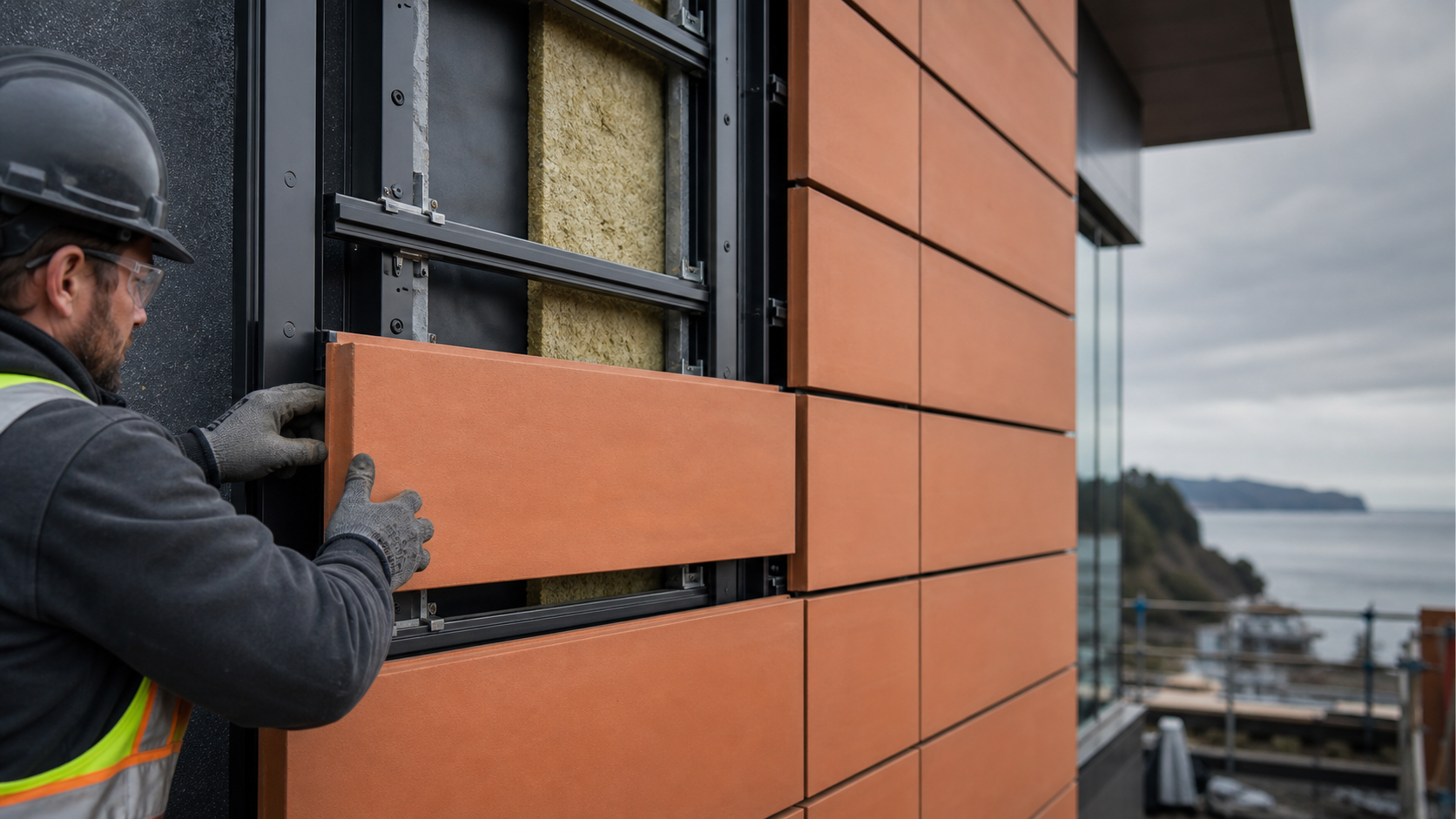
Representative terracotta cladding assembly
Representative installation visualization · Clip-supported terracotta facade
Original installation references and technical details
Scroll the installation · or press play
Representative sequence / Not to scale Interior ← Exterior →
01 / 07 — Prepare

Prepare

Ready the wall behind the facade.

Wall assembly
BreathableRain and air are controlled while vapour can move outward where the assembly is designed to dry.
Low permeanceRain and air are controlled while vapour movement is more restricted.
Supporting information

The detail is there when it is needed.

The animation leads. Project-specific technical information sits below it.

Technical note

Animations are representative and intended to explain general installation sequencing. Final construction must follow approved project drawings, specifications, engineering, consultant direction, manufacturer requirements, tested assemblies and applicable codes.

7-stage sequence transcript
  1. Prepare: Ready the wall behind the facade.
  2. Rail: Set the support plane true.
  3. Clip: Fit the concealed panel clips.
  4. Hang: Engage each terracotta unit.
  5. Align: Keep lines even and joints open.
  6. Vent: Leave the drainage cavity working.
  7. Service: Replace a unit without reopening the face.
Before construction

Final materials, fastening, transitions, flashing, substrates, continuity, engineering and project requirements must follow approved project documents and applicable requirements. Fig Philp Group Inc. should review the sequence against the selected system before construction.

Start a project conversation

See the assembly. Then send the drawings.

Share project drawings or request an exterior-cladding estimate from the Fig Philp Group Inc. team.

Representative installation sequence only — final construction follows approved project documents and applicable requirements.

  1. Prepare: Ready the wall behind the facade.
  2. Rail: Set the support plane true.
  3. Clip: Fit the concealed panel clips.
  4. Hang: Engage each terracotta unit.
  5. Align: Keep lines even and joints open.
  6. Vent: Leave the drainage cavity working.
  7. Service: Replace a unit without reopening the face.

Animated assembly sequence

Project-specific reference details and governing notes
Terracotta rainscreen — generic extruded hollow-cell terracotta panels hung on an aluminum sub-frame over a drained and ventilated cavity, cabinet-oblique assembly sequenceCabinet-oblique cutaway of a generic terracotta rainscreen wall: steel studs and sheathing, a vapour-permeable water-resistive air barrier with shingle laps, a sloped base flashing set at the barrier plane with the barrier lapped down over its back leg, a membrane-flashed rough opening and window, thermally broken clips with semi-rigid mineral wool, extruded aluminum vertical rails with one fixed point and sliding points, a perforated base inlet closure and a screened top-of-wall exhaust closure, sloped head and sill flashings with end dams and a drip kick, hanger clips with upturned noses plus starter and top restraint clips, extruded hollow-cell terracotta panels hung by continuous back grooves and locked by security clips, open labyrinth horizontal joints with an outward-falling ledge, open vertical joints with baffles on the rail lines, true inside- and outside-corner plan sub-scenes with one-piece L-shaped corner units, rising cavity airflow with intake low and exhaust high, water paths that always exit outward, a single-panel lift-out replacement sequence, and ten detail insets. Not to scale, illustrative; every dimension is held. TERRACOTTA RAINSCREEN — ASSEMBLY SEQUENCEFig Philp Group Inc. · Motion V1 · cabinet-oblique assembly — NTS, illustrative · generic system, no manufacturer depictedLAYER SEQUENCE BARRIER LAPPED SHINGLE-FASHIONSILL PAN UP / JAMBS OVER / HEAD OVER JAMBSWINDOW SCOPE:SEE NOTE 2BARRIER LAPS DOWNOVER THE BACK LEGCLOSED HEM – DRY SIDEBASE FLASHING AT BARRIER PLANE – NTS – HOLDHOLDS – NOTHING HERE IS DIMENSIONED01 SUBSTRATE + W-R BARRIER + BASE FLASHINGBARRIER LAPPED SHINGLE-FASHIONSILL PAN UP / JAMBS OVER / HEAD OVER JAMBS ANCHORED BACK TO STRUCTUREWOOL LANDS ABOVE THE BASE FLASHING SHELFONLY THE CLIP TABS STAY PROUD OF THE WOOL FACECLIP SPACING PER STRUCTURAL DESIGN – HOLD02 THERMAL CLIPS + MINERAL WOOLCLIPS ANCHORED THROUGH THE BARRIER PLANEANCHORS ILLUSTRATIVE – NOTE 3 FIXED POINTSLIDING POINTS – SLOTTEDTHERMAL MOVEMENT GAPRAIL SPLICE MOVEMENT GAP – NTS – HOLDRAILS FASTENED TO CLIP TABS – NOTE 303 ALUMINUM VERTICAL SUB-FRAMEONE FIXED POINT, SLIDING POINTS ELSEWHEREFASTENED TO CLIP TABS – NOTE 3 PERFORATED INLET CLOSURE – UPSTANDBEHIND THE PANEL PLANE, NEVER BENEATH ITSCREENED EXHAUST CLOSUREUNDER THE PARAPET / SOFFITHEAD FLASHING – UPTURNED END DAMSDRIP KICKJAMB PROFILE OVER SILL UPTURNPROFILE GEOMETRY + FREE AREA NTS – HOLD04 CAVITY CLOSURES + OPENING FLASHINGSINLET LOW, EXHAUST HIGH, BOTH SCREENEDNO LAP RUNS UPHILL HANGER CLIP – SPACING PER PROJECT DESIGNSTARTER RESTRAINT CLIP – BOTTOM COURSETOP RESTRAINT CLIPCLIP + RESTRAINT SPACING – NTS – HOLDHANGER CLIP + STARTER RESTRAINT (NTS)RAILUPTURNED NOSECOURSE ADJUSTMENT SLOTSTARTER RESTRAINT CLIP –BOTTOM COURSE WIND RESTRAINTCLIP FIXINGS ILLUSTRATIVE – NOTE 3CLIP SPACING: NTS – HOLD05 HANGER CLIPS + BASE RESTRAINTUPTURNED NOSES ENGAGE THE BACK GROOVESSTARTER RESTRAINT AT THE BOTTOM COURSE TERRACOTTA PANEL SECTION (NTS)UPPER BACK GROOVELOWER BACK GROOVEHOLLOW CELLS+ INTERNAL WEBSGROOVES ARE EXTRUDED,NOT CUTPANEL MODULE + THICKNESS: HOLDEXTRUDED HOLLOW-CELL TERRACOTTA – GENERIC – NTS06 TERRACOTTA PANEL SECTION (NTS)HOLLOW CELLS + INTERNAL WEBSGROOVES ARE EXTRUDED, NOT CUT LIFT, ENGAGE THE NOSES, SEATSECURITY CLIP LOCKS THE HANGERNO THROUGH-PANEL FASTENERSSECURITY-CLIP QUANTITY + PLACEMENT – HOLDUPPER GROOVE CARRIES DEAD LOADLOWER GROOVE TAKES WIND LOAD07 PANELS HUNG + SECURITY CLIPSDEAD LOAD ON THE UPPER GROOVENO THROUGH-PANEL FASTENERS – NOTE 3 OPEN HORIZONTAL JOINT – LABYRINTH (NTS)UPPER LIP LAPS OUTBOARDDRIVEN RAINAIR PASSES FREELYLEDGE FALLS OUTWARD – NO POCKETGAP + LAP DEPTH: NTS – HOLDNO SEALANT – JOINT STAYS OPEN08 OPEN HORIZONTAL JOINT – LABYRINTHSHIPLAP BAFFLE, NO STRAIGHT-LINE PATHLEDGE FALLS OUTWARD – NO POCKET VERTICAL JOINT (PLAN, NTS)OPEN VERTICAL JOINT – BAFFLE BEHINDBAFFLE ON THERAIL LINEWIDTH + ENGAGEMENT: NTS – HOLD09 VERTICAL JOINTS – BAFFLE BEHINDOPEN AT THE FACE, BAFFLED ON THE RAIL LINECROSSING WATER IS SENT DOWN THE CAVITY INSIDE CORNER (PLAN, NTS)INSIDE-CORNER SPECIAL UNITBAFFLED OPENJOINT AT THERE-ENTRANT LINEUNIT LEG LENGTHS: NTS – HOLDLAYER STACK TURNS THE CORNER – CONTINUOUS – NTSOUTSIDE CORNER (PLAN, NTS)ONE-PIECE L-SHAPED CORNER UNITBOTH LEGSGROOVEDCORNER CLIP SETBACK: NTS – HOLDLAYER STACK TURNS THE CORNER – CONTINUOUS – NTS10 CORNER UNITS – PLAN (NTS)ONE-PIECE L-SHAPED OUTSIDE UNITLAYER STACK TURNS THE CORNER INTAKE AT THE BASE CLOSUREEXHAUST AT THE TOP OF WALLEVERY PATH EXITS OUTWARDINLET + OUTLET FREE AREA – NTS – HOLD11 CAVITY VENTILATION + DRAINAGEAIR IN LOW, OUT HIGH, PLUS THE OPEN JOINTSEVERY WATER PATH EXITS OUTWARD LIFT CLEARANCE: NTS – HOLDINDIVIDUAL PANEL REPLACEABLE WHERE LIFT CLEARANCE IS PROVIDEDRELEASE SECURITY CLIPS FIRST – VERIFY PER PROJECT DESIGN12 PANEL REPLACEMENT – LIFT-OUTRELEASE SECURITY CLIPS, LIFT, ROLL OUTADJACENT PANELS UNDISTURBED 1HEAD2JAMB3SILL4BASE5TOP OF WALL6OUT CORNER7IN CORNER8H-JOINT9PANEL SECTIONHEAD (SECTION, NTS)VENTED CLOSURE KEEPS THE CAVITY OPENSCREENEDSLOPED FLASHINGEND DAMS EACH SIDESLOPE + CLEARANCE GAP: HOLDJAMB (PLAN, NTS)PANEL EDGE – JAMB PROFILE – FRAMEJAMB LAPS OVER THE SILL UPTURN,RUNS UNDER THE HEAD FLASHINGPROFILE WIDTH + FREE AREA: HOLDSILL (SECTION, NTS)SLOPED SILL FLASHING – UPTURNED ENDSDRIP KICKPANEL COURSE BELOW – CLEARANCE GAP,NO BEARING ON THE FLASHINGGAP + DRIP PROJECTION: HOLDBASE (SECTION, NTS)BARRIER LAPS DOWN OVER THE BACK LEGPERFORATEDINLET CLOSUREPANEL BEARS ON NOTHING – CLEARANCE GAPPROFILE + FREE AREA: HOLDTOP OF WALL (SECTION, NTS)PARAPET / SOFFIT LINE ABOVESCREENED EXHAUSTTOP RESTRAINT CLIPCAVITY OPEN TO THE EXHAUST CLOSURETERMINATION POSITION: NTS – HOLDNOTES – VERBATIMNOTE 1 – GOVERNANCEProject drawings, specifications, approved submittals, manufacturer instructions and applicablecodes govern. The FPG Detail Library is a controlled reference and generation resource and doesnot replace project-specific design or approval.NOTE 2 – SCOPE RESPONSIBILITYScope responsibility varies by project — coordinate with the approved responsibility matrix.NOTE 3 – FASTENERSFasteners shown are illustrative only. Type, material, spacing, embedment, edge distance andstructural capacity must follow the approved project design and manufacturer requirements.13 COMPLETE ASSEMBLYNINE CALLOUTS + IN-DRAWING NOTES BOXNTS, ILLUSTRATIVE – EVERY QUANTITY HELD

Transcript — the terracotta rainscreen sequence in words

A complete text equivalent of the animation. Every step is listed with its caption and a description of what the drawing shows. Nothing here depends on JavaScript.

  1. SUBSTRATE, W-R AIR BARRIER + BASE-OF-WALL FLASHING. Exterior sheathing over steel studs, covered by a vapour-permeable water-resistive air barrier lapped shingle-fashion; the sloped base flashing is set on the barrier plane first with the barrier lapped down over its back leg, and the rough opening is membrane-flashed — sill pan up, jambs over, head over jambs — before the window is set into the protected opening. Scope responsibility varies by project — coordinate with the approved responsibility matrix.Drawn: steel studs and tracks on the cut edge, sheathing with the rough opening pre-cut, the water-resistive air barrier over the field with dashed shingle laps returning into the reveal, the base flashing set on the barrier plane with its back leg up and the barrier lapped down over it (shingle arrow), the outward-sloped shelf, face and closed dry-side hem, then the sill pan, jamb strips and head strip in shingle order and the window unit marked WINDOW SCOPE: SEE NOTE 2. HOLD chip: BASE FLASHING AT BARRIER PLANE – NTS – HOLD.
  2. THERMAL CLIPS + MINERAL WOOL. Thermally broken clips anchored through the barrier plane back to structure, then semi-rigid mineral-wool insulation fitted tight between and around the clips and landing above the base flashing shelf — only the clip tabs stay proud of the insulation face.Drawn: thermally broken clip assemblies on the barrier plane — base plate, anchor markers, thermal spacer arm and outer tab — with an attachment-direction arrow into structure; hatched semi-rigid mineral wool fills the field, returns into the reveals and lands above the base flashing shelf, with only the clip tabs proud of the wool face. HOLD chip: CLIP SPACING PER STRUCTURAL DESIGN – HOLD.
  3. ALUMINUM VERTICAL SUB-FRAME. Extruded aluminum vertical rails fastened to the clip tabs form the plumb support plane for the terracotta; each rail is held at one fixed point with sliding points elsewhere, so the aluminum can move thermally without distorting the panel plane.Drawn: extruded aluminum vertical rails landing on the clip tabs in columns, interrupted at the window opening and stopping short of the top-of-wall closure line; rail-to-clip fastener markers at every tab; one fixed-point symbol and slotted sliding points on a rail; a dashed movement gap at a rail splice. HOLD chip: RAIL SPLICE MOVEMENT GAP – NTS – HOLD.
  4. CAVITY CLOSURES + OPENING FLASHINGS. The cladding-plane closures go on before any panel hangs: a perforated inlet closure at the base whose shelf runs into the cavity and whose upstand sits behind the coming panel plane; a screened exhaust closure at the top of the wall; at the window a sloped head flashing with upturned end dams and a sloped sill flashing with a drip kick and upturned ends, each lapped by the jamb profiles so no lap runs uphill.Drawn: the perforated base inlet closure mounted to the sub-frame above the step-1 base flashing, shelf into the cavity and upstand behind the panel plane; the screened exhaust closure under the parapet or soffit line at the top of wall; the sloped head flashing with upturned end dams; the sloped sill flashing with kicked hem and upturned ends; jamb profiles lapping over the sill upturns. HOLD chip: PROFILE GEOMETRY + FREE AREA NTS – HOLD.
  5. HANGER CLIPS + BASE RESTRAINT. Panel hanger clips fix to the rail faces — each presents an upturned nose shaped to engage the continuous extruded groove in the panel back, with adjustment slots so a whole course can be levelled before lock-off; at the first course line a starter restraint clip is set to take the bottom groove of the bottom panel, which has no course beneath it.Drawn: rows of hanger clips on the vertical rails at every course line, a differently drawn starter restraint clip at the lowest course line and a top restraint clip at the final course line, plus a zoom inset showing one clip in profile — rail face, clip body, slotted fixing and upturned nose, with the starter restraint below it. HOLD chips: CLIP + RESTRAINT SPACING – NTS – HOLD and CLIP SPACING: NTS – HOLD.
  6. TERRACOTTA PANEL SECTION (NTS). A section through the extruded terracotta panel: internal webs form hollow cells that keep the fired clay light and stiff, and the top and bottom of the panel back carry continuous extruded grooves — the panel’s own hanging geometry, formed in the extrusion, not cut. Panel module and thickness are NTS — HOLD.Drawn: a true vertical section through one panel — outer face, internal webs, hatched hollow cells, and the continuous upper and lower back grooves drawn as extruded re-entrant channels, labelled EXTRUDED HOLLOW-CELL TERRACOTTA – GENERIC – NTS. HOLD chip: PANEL MODULE + THICKNESS: HOLD.
  7. PANELS HUNG + SECURITY CLIPS. Panels hang bottom course first: each panel’s upper back groove drops over the clip noses and carries its dead load, while its lower groove locates against the clips of the course below for wind restraint — the bottom course taking the starter restraint clip instead. No fastener ever passes through the terracotta; security clips then lock the hangers so wind suction or impact cannot lift a panel off its supports.Drawn: the cavity on the cut, then courses of panels seated on the clip noses with a lift-engage-seat motion arrow; the panel-section inset gains clip noses in both grooves with UPPER GROOVE CARRIES DEAD LOAD and LOWER GROOVE TAKES WIND LOAD; a security clip locks a hanger; field label NO THROUGH-PANEL FASTENERS. HOLD chip: SECURITY-CLIP QUANTITY + PLACEMENT – HOLD.
  8. OPEN HORIZONTAL JOINT — LABYRINTH. The horizontal joint stays open — no sealant — but the meeting edges are shiplapped into a labyrinth: the upper panel’s bottom lip laps outboard of the lower panel’s top upstand, so driven rain has no straight-line path to the cavity, while the ledge between them falls outward so anything caught there sheds back out and air still moves freely through the joint. Joint gap and lap depth NTS — HOLD.Drawn: a zoom section at a horizontal joint — the upper panel’s outboard bottom lip lapping outside the lower panel’s inboard top upstand, the offset overlap forming the baffle, and the ledge between the lips falling outward; a dashed rain arrow enters, strikes the labyrinth and exits outward over the ledge while a separate air arrow passes through freely. HOLD chip: GAP + LAP DEPTH: NTS – HOLD.
  9. VERTICAL JOINTS. Vertical joints are open at the face with an aluminum baffle profile behind, running on the rail line — any water crossing the joint meets the baffle and is directed down the cavity instead of reaching the barrier. Joint width and baffle engagement each side NTS — HOLD.Drawn: the vertical joint lines completed across the elevation, plus a plan bubble at a vertical joint — two panel edges, the open gap, the aluminum baffle profile clipped to the rail behind it, dashed engagement each side, and a dashed water arrow deflecting down the baffle into the cavity. HOLD chip: WIDTH + ENGAGEMENT: NTS – HOLD.
  10. CORNER UNITS — PLAN (NTS). Corners use true special units: at the arris an L-shaped extruded corner panel turns the corner in one piece of terracotta — not a cut mitre glued at the face — and the re-entrant inside corner uses its own special unit, with rails, clips, the open-joint lines and the ventilated cavity all continuous around both returns.Drawn: two plan insets. OUTSIDE CORNER (PLAN, NTS) — both wall planes meeting at the arris with the full layer stack turning the corner and a one-piece L-shaped terracotta corner unit wrapping the arris on corner clips, its setback dashed. INSIDE CORNER (PLAN, NTS) — the re-entrant junction with a continuous stack and an inside-corner special unit on rails both sides with a baffled open joint. HOLD chips: CORNER CLIP SETBACK: NTS – HOLD and UNIT LEG LENGTHS: NTS – HOLD.
  11. CAVITY VENTILATION + DRAINAGE. Air enters at the perforated base closure and through the open joints, rises in the cavity behind the panels and leaves through the screened exhaust closure at the top of the wall; water that passes the labyrinth drains down the rail line, over the sloped base flashing set at the barrier plane and out past the hemmed drip — every path exits outward, never inward.Drawn: an intake arrow at the perforated base closure, rising airflow chevrons in the cavity (animated while playing, static when complete), an exhaust arrow leaving through the screened top-of-wall closure, and three dashed water paths — from a horizontal joint down the cavity onto the base flashing and off the hem, onto the head flashing and out between its end dams, and off the sill drip kick clear of the course below. HOLD chip: INLET + OUTLET FREE AREA – NTS – HOLD.
  12. PANEL REPLACEMENT — LIFT-OUT. Because panels hang rather than fasten through, a damaged panel can be taken out on its own where the system provides the vertical lift clearance to disengage the grooves: release its security clips, lift the panel until the upper groove clears the clip noses, roll the bottom edge clear and hang the replacement. Required lift clearance and clip access are NTS — HOLD, and govern whether adjacent panels must be disturbed.Drawn: one mid-field panel highlighted in the accent colour, the required vertical travel drawn as a dashed witness dimension carrying no value, a ghosted outline of the lifted position, and the note that security clips are released first and adjacent panels stay undisturbed. HOLD chip: LIFT CLEARANCE: NTS – HOLD.
  13. COMPLETE ASSEMBLY. Finished assembly — NTS, illustrative. Callouts: head / jamb / sill / base / top of wall / inside corner / outside corner / horizontal joint / panel section.Drawn: the finished elevation with nine numbered callout rings — head, jamb, sill, base, top of wall, outside corner, inside corner, horizontal joint and panel section — the five remaining zoom insets (head section, jamb plan, sill section, base section, top-of-wall section), and the in-drawing NOTES – VERBATIM box carrying Notes 1 to 3 word for word.

Governing notes (verbatim)

Note 1 — governance. Project drawings, specifications, approved submittals, manufacturer instructions and applicable codes govern. The FPG Detail Library is a controlled reference and generation resource and does not replace project-specific design or approval.

Note 2 — scope responsibility. Scope responsibility varies by project — coordinate with the approved responsibility matrix.

Note 3 — fasteners. Fasteners shown are illustrative only. Type, material, spacing, embedment, edge distance and structural capacity must follow the approved project design and manufacturer requirements.

Note 4 — NTS / HOLD. No numeric dimension is shown for this system. Geometry is NTS, illustrative — HOLD pending project drawings, approved shop drawings and manufacturer requirements. Figures published for other systems on other pages are project-specific and are not reused here.

Note 5 — generic identity. The cladding is labelled as a generic extruded hollow-cell terracotta panel. No product, manufacturer or brand is depicted or implied. Panel format, cell arrangement, groove geometry, corner-unit availability and the permitted replacement method vary by system and must be confirmed against the approved submittal.

Note 6 — performance values. No thermal, airflow, wind-pressure or fire figure is shown numerically anywhere in this component; comparative arrows and qualitative language only.